Anatomy of a Proactive Well Servicing Regimen Part 3: Failure Type / Equipment Selection
- Kalcy Thomas
- Aug 19, 2020
- 5 min read
In this part of the series, I will discuss why it is important to properly identify what actually failed. Proper diagnosis not only allows you to choose the most effective type of services for the repair (as discussed previously), but it also affords you the opportunity to start sourcing out replacement equipment ahead of time. Thorough preparation will save significant $$ over the course of a repair, by avoiding standby charges and giving you some time to "shop around" for replacement parts. This also leads into some detail on how to minimize the risk of future failures by selecting the proper equipment for the application at hand.
Equipment Categories
The main components in a typical reciprocating pump, artificial lift system are the pump, rods and tubing. And while this would seem straight forward to diagnose which component failed, there are actually many different things that can go wrong with each piece. With a proper inspection, you can diagnose exactly what went wrong and adjust your design to avoid any recurrence. But without a thorough equipment inspection you won't be able to improve the situation, that's why it's important to do the inspection prior to installing new equipment in the ground.
BHP - There are many different components within a typical bhp (bottomhole pump), which means there are many things that can go wrong. Some examples of bhp failures I've encountered over the years are as follows:
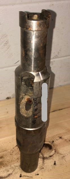
i. Worn travelling guide/rod - typically caused by a deviation or inclination where the pump is landed. You can either move the pump depth, or change the equipment composition and/or the lining on the guide to prevent future occurences. The picture below shows how severe side loading can wear right through a travelling guide.
ii. Damaged top end - typically due to tapping the pump on an ongoing basis. This is fixed by changing the operational philosophy rather than an equipment change, although there are some pumps out there that are designed to run on tap. These pumps have specific shock absorbers to prevent permanent damage.
iii. Seized due to scale - scaling tendencies can change over time, typically due to changes in watercut, water flood breakthrough, batching chemicals/fluids, etc. You can design around this by coating pump components accordingly, or introducing a chemical program.
iv. Seized due to sand - there are only thousands of an inch of clearance between the pump and barrel, so it doesn't take much sand to seize a pump. Your best protection against this would be to add a sand screen and/or sand catcher below the pump. You can also run different barrel types/clearances/sizes to cope with sand.
v. Worn barrel, plunger, valves, seats, etc. - typically occur due to regular wear and tear. But if you are finding premature wear, you can upgrade the composition of any component to increase run time.
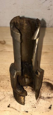
vi. Asphaltene buildup. This occurs over time, and will either cause the pump to seize, or block the flow path through the pump. The best way to combat this problem is a good chemical program. The picture below is an example of the flow path getting plugged off.
Rods & Tubing - Since these two components are constantly in contact, the types of failures and methods to mitigate, are quite similar. Although they both seem like fairly straightforward components of the system due to the lack of moving parts, many different things can go wrong. You can have failures on the polished rod, sucker rods, sinker bars, rod couplings, tubing joints, pup joints, blast joints, tubing collars, etc. Typically these failures are due to corrosion, wear, exceeding tensile strength, or wax buildup.
i. Corrosion - If the failure was due to corrosion, material selection is very important to maximize run life. You need to choose one that will withstand the environment it will be located in. If you are forced to run something in an unsuitable environment, chemical inhibition programs can help combat corrosion if selected and administered properly. You can also put coatings on tubing and rodstrings, although that can become quite pricey.
ii. Wear - The most common way to combat friction and wear would be to add scrapers/centralizers to your rodstring. This prevents metal on metal contact, which prolongs the life of both components. Some other solutions to prolong run life are using harder materials, tbg/rod rotators, or simply slowing down the pumpjack (if possible.)
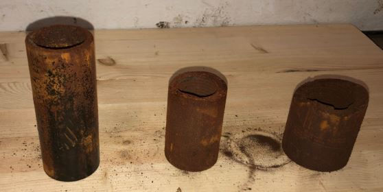
When diagnosing a failure along these 2 components, some important details to consider are the location and type of failure. By examining the failure point and the faces of each side of the part, you can usually determine what caused it. The failure could be the result of a manufacturer defect, improper materials, exceeding specs, a reaction with the environment (sulfide stress crack), etc. The location of the failure along the piece of equipment also assists proper diagnosis, so you want to take note if it occurred on the shoulder, coupling, body, etc. The pictures below give a few examples of worn and parted rod couplings as well as a corroded tubing collar. If coupling wear is a problem in your wellbore, please get in touch as I have recently discovered a new hardening process that will increase your run life substantially.

Equipment Selection
Many factors come into play when selecting what equipment to use in your wellbore. Some of the deciding factors are related to the failure mechanisms above, while others are related to what you want to achieve with your artificial lift system and the theoretical design you build beforehand. Whether you use SROD, Rodstar or some other comparable software, you should build a BHA (bottomhole assembly) design to ensure you can accomplish what you would like with your artificial lift system. You want to ensure the equipment you order and have available can handle what you desire.
Pumpjack - You want to ensure your structure, gearbox and motor are sufficient to support everything below. If you find your rodstring is too heavy, you can utilize smaller diameter and/or fibreglass rods to reduce the load. You can also adjust your pump size accordingly.
Motor - your design will let you know how much HP you require to drive the pumpjack, so ensure you have a big enough prime mover to do the job.
Polished Rod / Rodstring - You want to make sure each rod taper is capable of carrying the load required. Side loading, tension and compression are all important considerations that must be taken into account. Material selection is also very important, I have dealt with everything from high CO2 to high H2S, and there's a different material for every situation.
Tubing - You want to make sure the tubing size you use will accommodate a big enough pump to provide the volumes required. (Preferably you want to be able to run top hold down pumps, so keep that in mind.) On the other hand, you want to give yourself some options down the road, so keep in mind that the well conditions can change and you might end up running a plunger down the road, so don't go too big.
Pump - You want to make sure your pump design will deliver the volume you want, and you also want to be sure that you have enough stroke downhole to accomodate what you have at surface on the pump jack. Fibreglass rods will also effect this, as you get a slingshot effect and plunger overtravel, so be aware. Review the deviation and inclination where you land the pump, and avoid any troubles areas.
Conclusion
This gives a pretty good outline of some things to take into consideration when designing and repairing rod pumping systems. Of course there are other considerations to take into account which I have glossed over here. But all of those fine details come with experience. Having a basic understanding of all of the above items provides a solid framework to make important decisions when working on wells.
If you would like some assistance ensuring your wellbores are properly designed and repaired, please get in touch.
Thanks, Kalcy
(403)391-3758

Comments